1 Setup and Hold Analysis
Definitions
sE = the (external) setup time, i.e. the setup time of the device containing the flip flop.
hE = the (external) hold time, i.e. the setup time for the device containing the flip flop.
sI = the setup time of the flip flop.
sX = the actual setup time of the flip flop where X = A, B, C, …
hI = the hold time for the flip flop.
hX = the actual hold time for the flip flop where X = A, B, C, …
dE
= the data external pin.
cE = the clock external pin.
dI = the flip flop data input.
cI = the flip flop clock input.
yD = the delay of the data from the external pin to the flip flop data input.
yC = the delay of the clock from the external pin to the flip flop clock input.
dE + yD = dI
cE
+ yC = cI
z = yD - yC
active edge = the edge (rising, falling) of the clock that loads the data input into the flip flop.
In this document, the rising edge of the clock is assumed to be the active edge for the flip flop.
Figure 1‑1 shows the timing variables of a typical flip flop. Figure 1‑2 shows the simplest case, the latest time at which the data can transition before the active edge of the clock if yD and yC both are 0. The data must transition at least sA, the setup time for the flip flop, before the active edge. In this case, the waveforms for both dE and dI are identical. Likewise, the waveforms for both cE and cI are identical
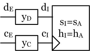
Figure 1‑1 Flip Flop Timing Variables
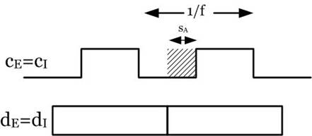
Figure 1‑2 Setup Time With yD = yC = 0
Likewise, Figure 1‑3 shows the simplest case, the earliest time at which the data can transition after the active edge of the clock if yD and yC both are 0. The data must transition at least hA, the hold time for the flip flop, after the active edge. In this case, the waveforms for both dE and dI are identical. Likewise, the waveforms for both cE and cI are identical
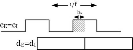
Figure 1‑3 Hold Time With yD = yC = 0
Figure 1‑4 shows the case where yD and yC are > 0. The data must transition at least sE before the active edge of cE, the external clock pin. In this case, the waveforms for both dE and dI are not identical due to yD. Likewise, the waveforms for both cE and cI are not identical due to yC. Note that an increase/decrease in yD makes sE larger/smaller and an increase/decrease in yC makes sE smaller/larger.
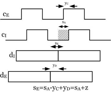
Figure 1‑4 Setup Time With yD > 0, yC > 0
Figure 1‑5 also shows the case where yD and yC are > 0. The data must transition at least hE after the active edge of cE, the external clock pin. In this case, the waveforms for both dE and dI are not identical due to yD. Likewise, the waveforms for both cE and cI are not identical due to yC. Note that an increase/decrease in yD makes hE smaller/larger and an increase/decrease in yC makes sE larger/smaller.
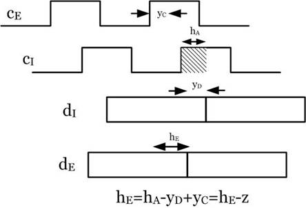
Figure 1‑5 Hold Time With yD > 0, yC > 0
Figure 1‑6 shows how yD, yC affect the setup and hold for a real device.
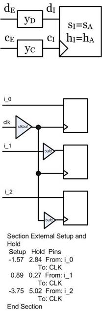
Figure 1‑6 Example
2 Setup and Hold Example
Figure 2‑1 illustrates how the external setup and hold is modified by the data and clock delays. Note that the setup and hold regions remain contiguous, but shifted by yD-yC = z. Note also that hE<0, i.e. it is the distance from the rising clock edge to the rightmost edge of the hA region. Region M is the region where the flip flop may go metasatble. Region N is the region where the flip flop will change state not on cE0, but on the next cE clock cycle.
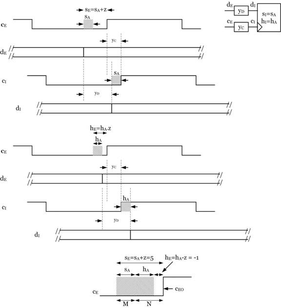
Figure 2‑1 Example
3 Setup And Hold Requirements: MIN Or MAX?
If the required setup and hold times are a max, then the actual setup and hold times of the device will meet the requirement if they are less than the required setup and hold. If setup and hold are a min, then the actual setup and hold of the device will meet the requirement if they are greater than the required setup and hold.
Which is it? Well if
I tell my friend that I will meet him at the
I will get there in < 2 hours
Now if I tell my friend that it will take me at least 2
hours to get to the
I will get there in > 2 hours
Definitions
sER = the required setup
sEA = the actual setup
Figure 3‑1 shows that if the data transitions anywhere in the sEA time internal, the data violates the actual setup time of the device. sER is defined as the minimum setup time the actual data is capable transitioning before the clock. This means that if sEA < sER, the actual data is guaranteed to transition before sEA, since it cannot transition before sER by definition. Therefore, if
sEA < sER
the setup requirement of the device is met and therefore
sER is a MAX
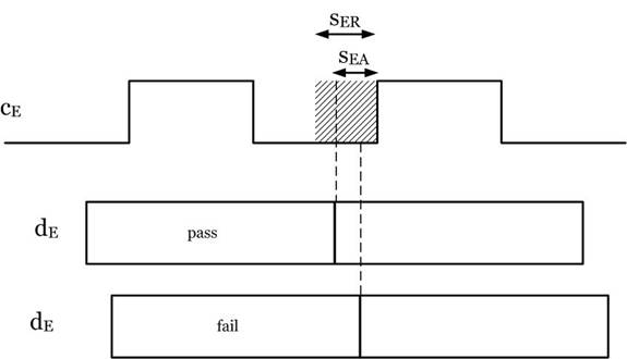
Figure 3‑1 Required And Actual Setup
If sER was a MIN, any value of sEA greater than sER would meet the requirement, which as illustrated in Figure 3‑1, would not meet the requirement.
Figure 3‑2 shows that if the data transitions anywhere in the hEA time internal, the data violates the actual hold time of the device. hER is defined as the minimum hold time the actual data is capable transitioning after the clock. This means that if hEA < hER, the actual data is guaranteed to transition after hEA, since it must transition after hER by definition. Therefore, if
hEA < hER
the hold requirement of the device is met and therefore
hER is a MAX
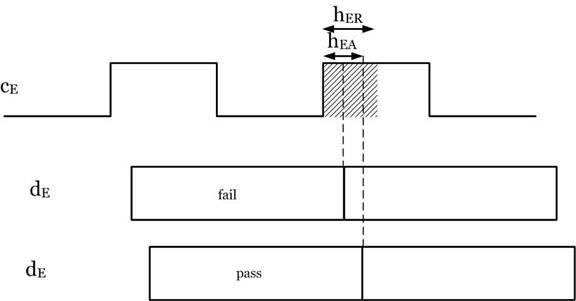
Figure 3‑2 Required And Actual Hold
If hsER was a MIN, any value of hEA greater than hER would meet the requirement, which as illustrated in Figure 3‑2, would not meet the requirement.